Introduction #
This guide will take you step-by-step through the manufacturing of a CNC box using just one bit and one flat setup on your CNC.
The CNC box is designed to be made of plywood, though any flat material would work. With no exposed joinery on the sides, these make attractive, easy, and sturdy drawer boxes.
Although this guide is comprehensive on using the basic features of this parametric file, it cannot cover all of the advanced features of Autodesk Fusion. If you have questions or comments, as always you can reach out via email at j.workmandm@gmail.com.
What you need: #
| Materials |
|---|
| Plywood (big enough to fit all pieces of your box) |
| 23Ga or 18Ga pin nails (optional) |
| Wood Glue (optional) |
| Tools |
|---|
| CNC Router |
| Straight Bit (recommended 1/8″ or 1/4″ compression bit) |
| Pin nailer or clamps |
Step 1: Download and open the file in Autodesk Fusion #
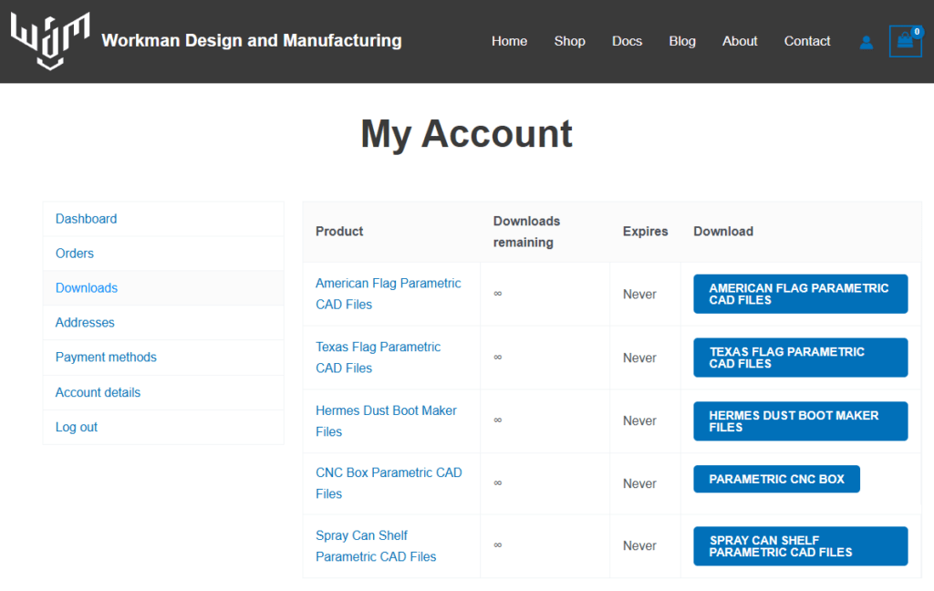
Step 1.1
- Download the file from
workmandm.com/my-account/downloads/ - If you did not create an account you can download it from the email sent with your order.
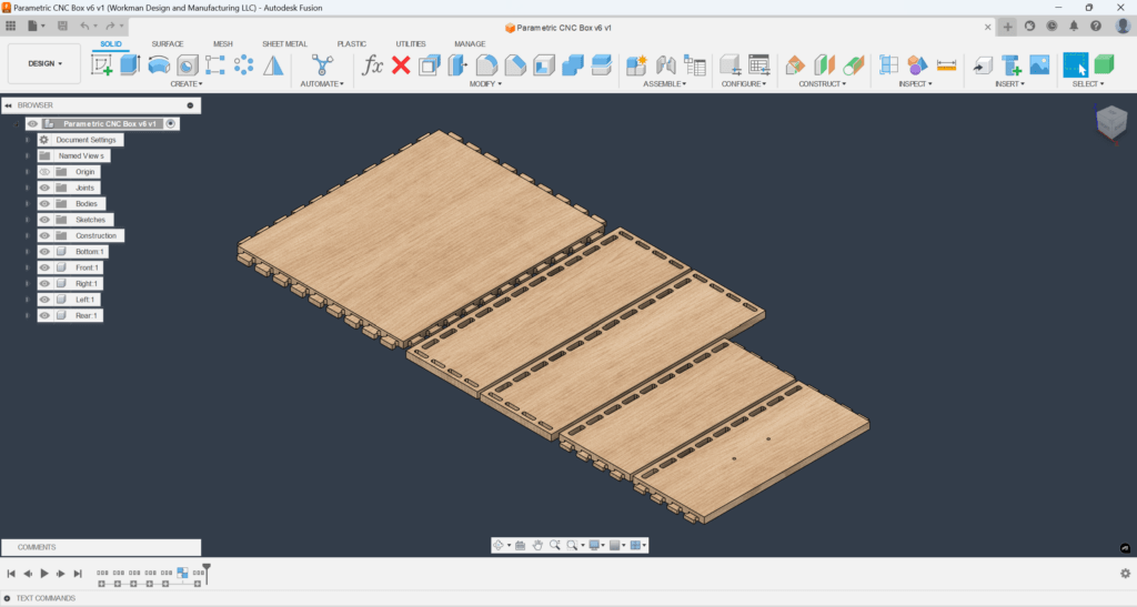
Step 1.2
- Open the file in Autodesk Fusion and save it.
- You may want to save a copy for each different size of drawer you intend to create.
Step 2: File usage #
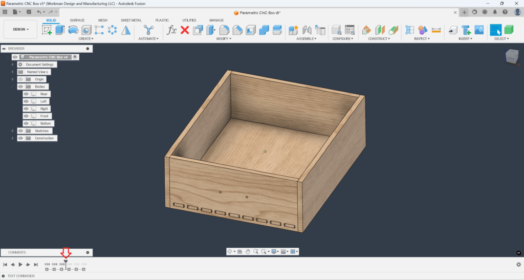
Step 2.1
- By default the file is configured as a flat pack for manufacturing. Roll the history marker to the red arrow as shown so that you can see the actual 3D size.
- The 3 groups that are suppressed turn the bodies into components, apply joints, and create surfaces for the CAM respectively.
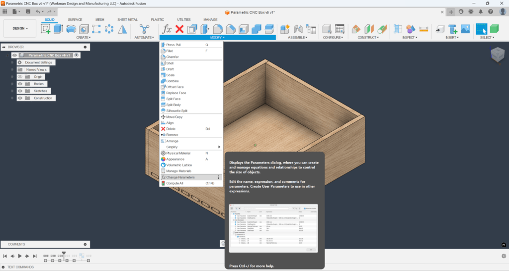
Step 2.2
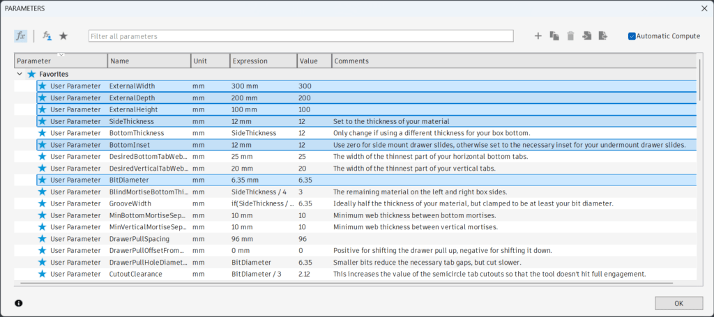
- Open the parameters dialog by clicking the Modify Dropdown>Change Parameters
Step 2.3
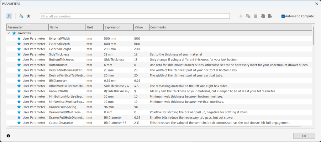
- The parameters control all of the features of the box. The main ones that may need to be changed are “ExternalWidth”, “ExternalDepth”, “ExternalHeight”, “SideThickness”, “BottomInset”, and “BitDiameter”.
- Note: Extreme values can cause errors. Stick to realistic plywood sizes (12mm, 15mm, 18mm) and keep the box bigger than 100x100x100mm^3.
- Note: If you prefer, you can put in dimensions with imperial units such as 1″ or 5 1/4 in
Step 2.5
- For the other parameters, refer to the “Comments” to understand how that parameter will affect the model.
- Some more detailed advice:
- For “SideThickness” Measure your material precisely with calipers. Plywood can shrink over time, which would result in a looser fitting joint.
- If your “BottomThickness” is less than 12mm, it is recommended to set “BottomInset” to at least 6mm.
- Your “BitDiameter” must be less than your “BottomThickness” and less than your “SideThickness”
- The smaller your “BitDiameter”, the smaller the clearance cutouts (visible at the front and rear of the box) will need to be. It is recommended to use a 1/4″ endmill or smaller.
- “GrooveWidth” determines how thick the vertical tabs will be and should not need to be adjusted.
Step 3: Example Parameter Adjustment #
Step 3.1
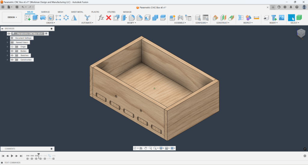
- As an example, we will change only the following parameter values resulting in the box shown on the left:
- External Width = 300mm
- External Depth = 200mm
- Exteral Height = 100mm
- SideThickness = 12mm
- BottomInset = 12mm
- BitDiameter = 1/4″
Step 3.2
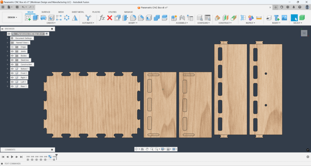
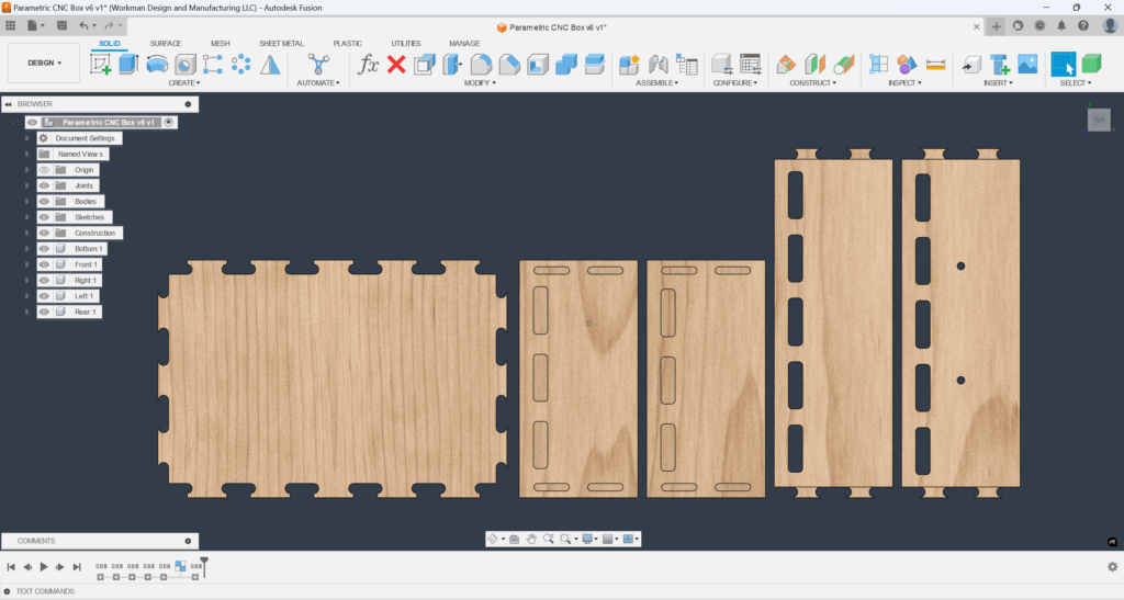
- If we slide the history marker to the end, we see that there is only a single vertical tab on each corner.
Step 3.3
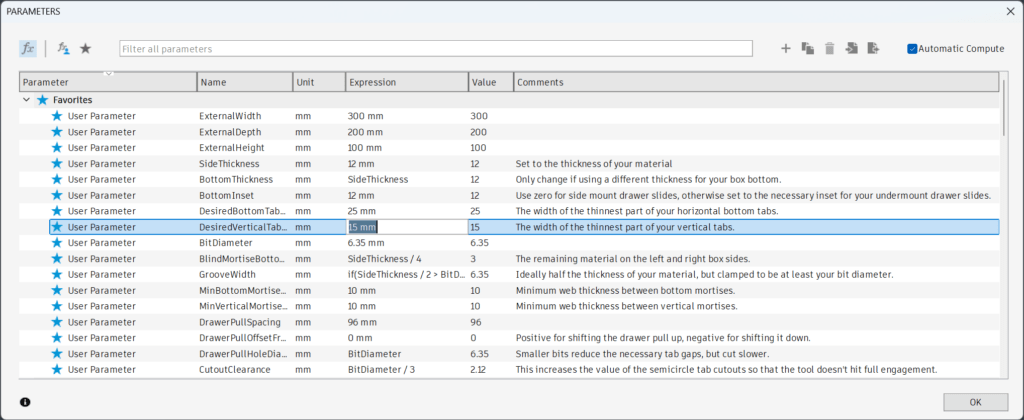
- Change the parameter “DesiredVerticalTabWebWidth” to 15mm.
Step 3.4
- By reducing the “DesiredVerticalTabWebWidth”, two tabs can now fit on each corner.
- You can also change “MinVerticalMortiseSeparation” to achieve a similar result.
Step 3.5
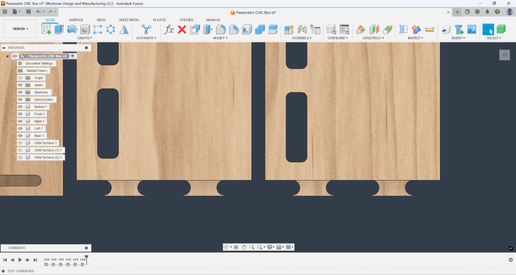
- Notice how the vertical tabs taper into extremely sharp points. This is caused by the fact that our bit diameter is nearly as large as the width of the vertical tabs.
- Note: The semicircular cutout (dogbone) is necessary for the joint to fully seat.
Step 3.6
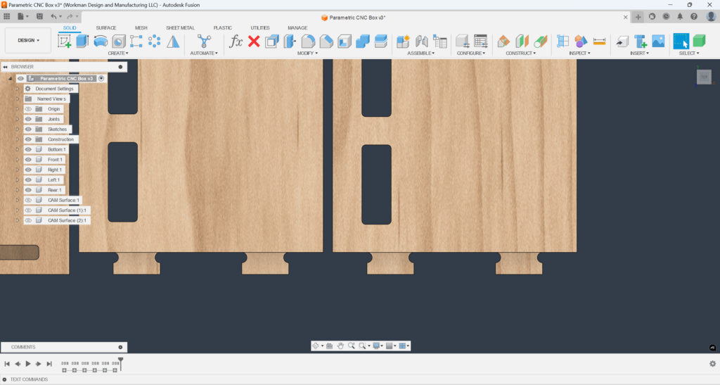
- Reduce the “BitDiameter” to 1/8″ to remedy the issue.
- Note: Smaller bit diameters result in smaller dogbones and smaller required clearance gaps.
Step 4: CNC CAM Setup #
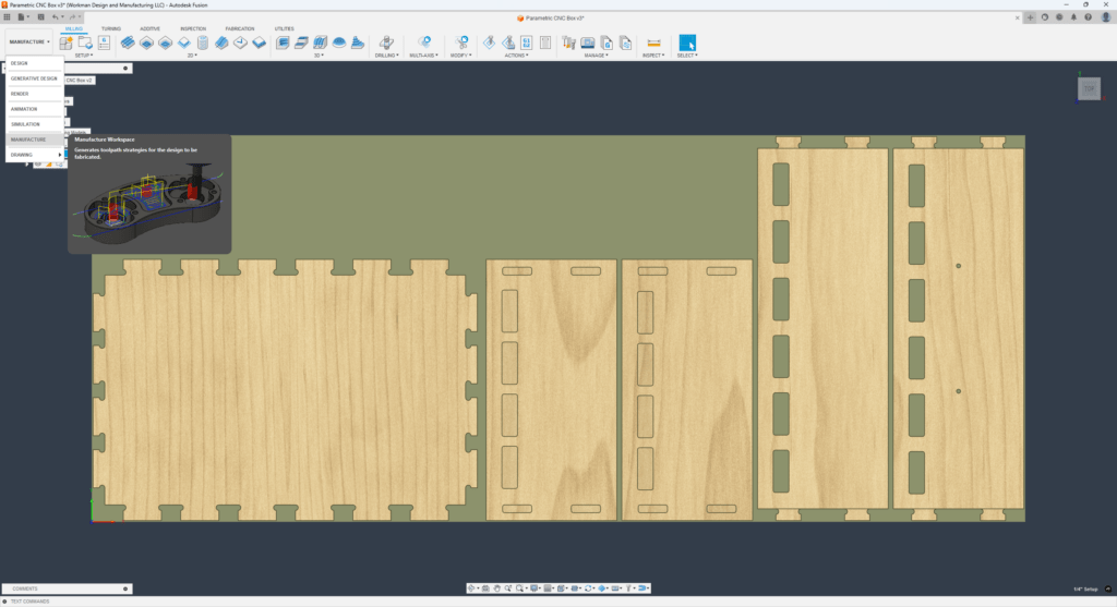
Step 4.1
- We will continue using the example from Step 3 for our CAM programming. For reference, we are using these parameters:
- External Width = 300mm
- External Depth = 200mm
- External Height = 100mm
- SideThickness = 12mm
- BottomInset = 12mm
- DesiredVerticalTabWebWidth = 15
- BitDiameter = 1/8″
- Switch over to the manufacturing workspace by clicking the workspace dropdown on the top left.
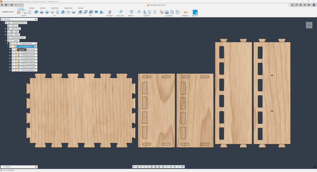
Step 4.2
- There are two different setups: one for 1/4″ bits and one for 1/8″ bits.
- Activate the setup for 1/8″ bits by clicking the dot on the right of the setup.
- Note: For other bit diameters, pick one setup and then you will need to manually edit each operation and switch the tool. Fusion currently does not have a faster option.
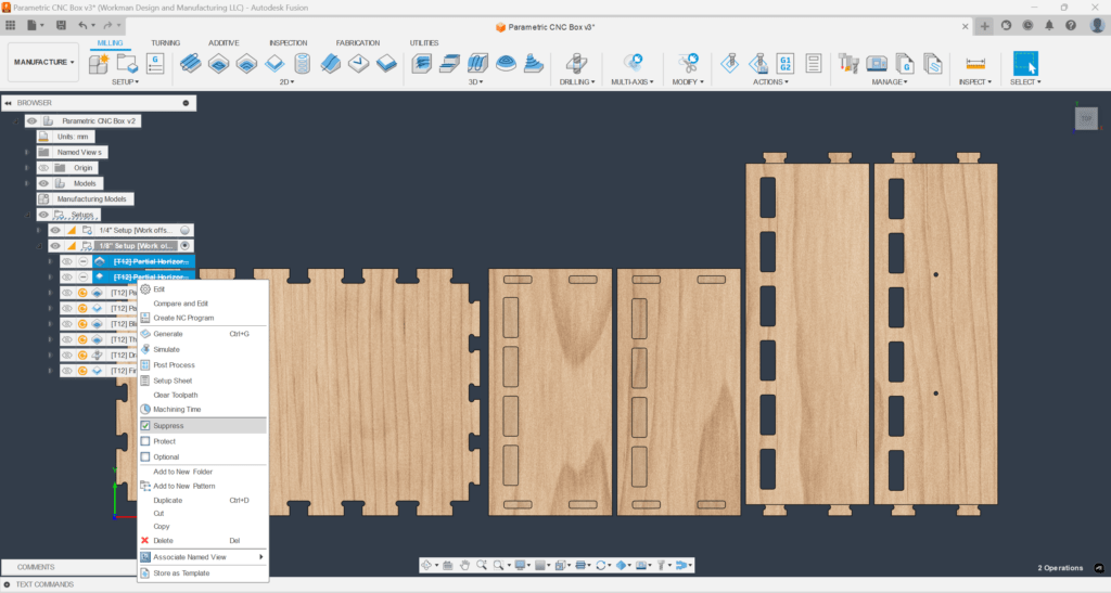
Step 4.3
- If your bottom panel has partial thickness tabs (unlike our example), skip this step.
- Right click on the first two operations and click suppress, since our bottom panel has full-thickness tabs.
- Note: This is dependent on the bottom inset. If “BottomInset” is between 0 and the thickness of your material, your bottom panel will have partial thickness tabs.
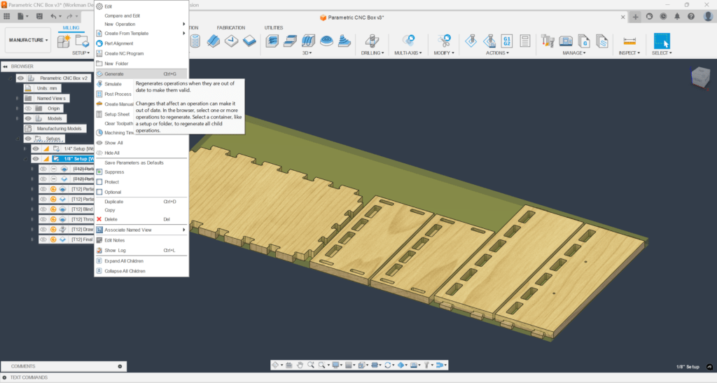
Step 4.4
- Right click on the setup and click “Generate” to regenerate the remaining toolpaths.
- We’ll now go over each toolpath individually
Step 5: CNC Toolpaths #
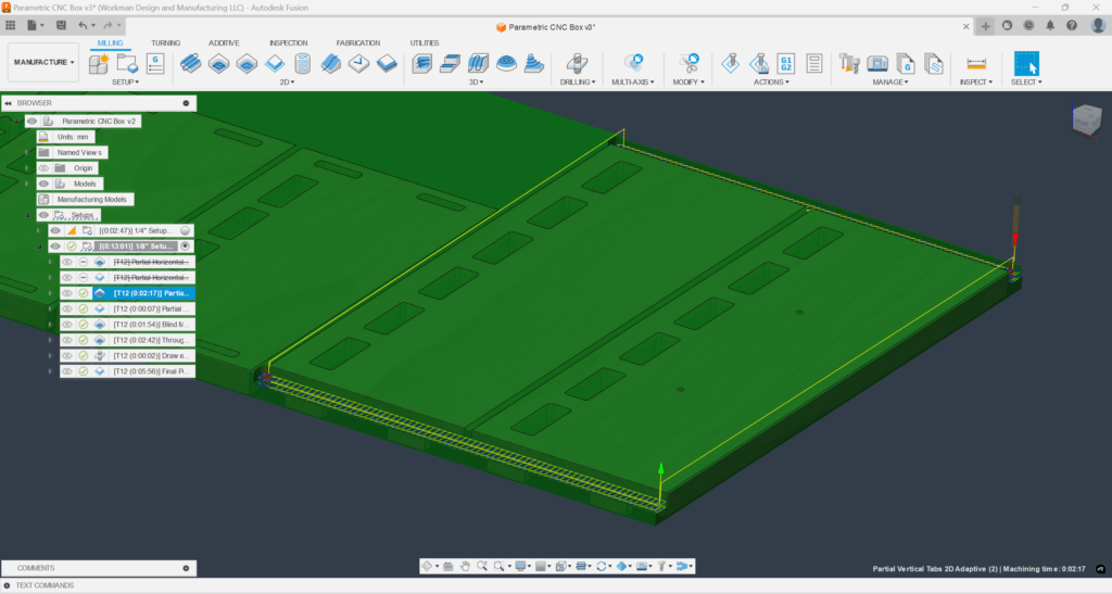
Step 5.1
- Partial Vertical Tabs 2D Adaptive
- This toolpath clears away the excess material from the vertical tabs.
- Note: The first suppressed toolpath is identical to this toolpath except that it cuts partial thickness tabs on the bottom panel.
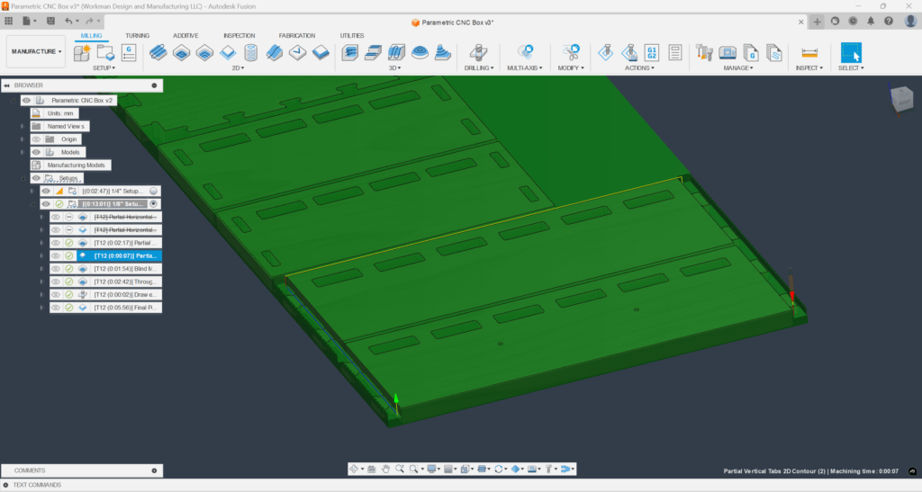
Step 5.2
- Partial Vertical Tabs 2D Contour
- This toolpath creates a perfectly straight edge and cleans up the rough shoulder from the 2D Adaptive.
- Note: The second suppressed toolpath is identical to this toolpath except that it cleans up the shoulder on the bottom panel.
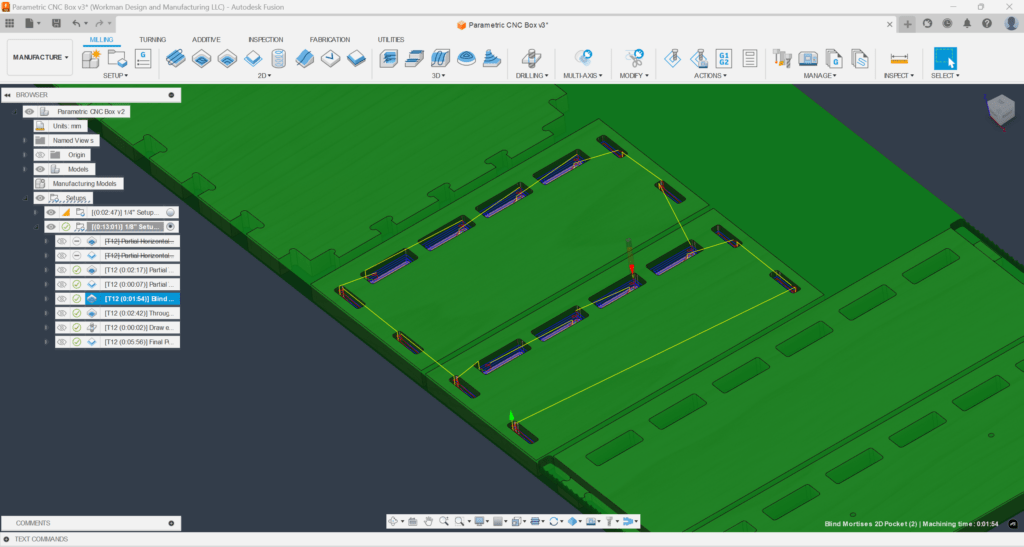
Step 5.3
- Blind Mortises 2D Pocket
- This toolpath cuts the blind mortises in the two side pieces
- Note: There is a slight negative axial stock to leave so the pocket is cut a bit deeper which allows the shoulders of the front and back to mate flush with the faces of the sides and bottom
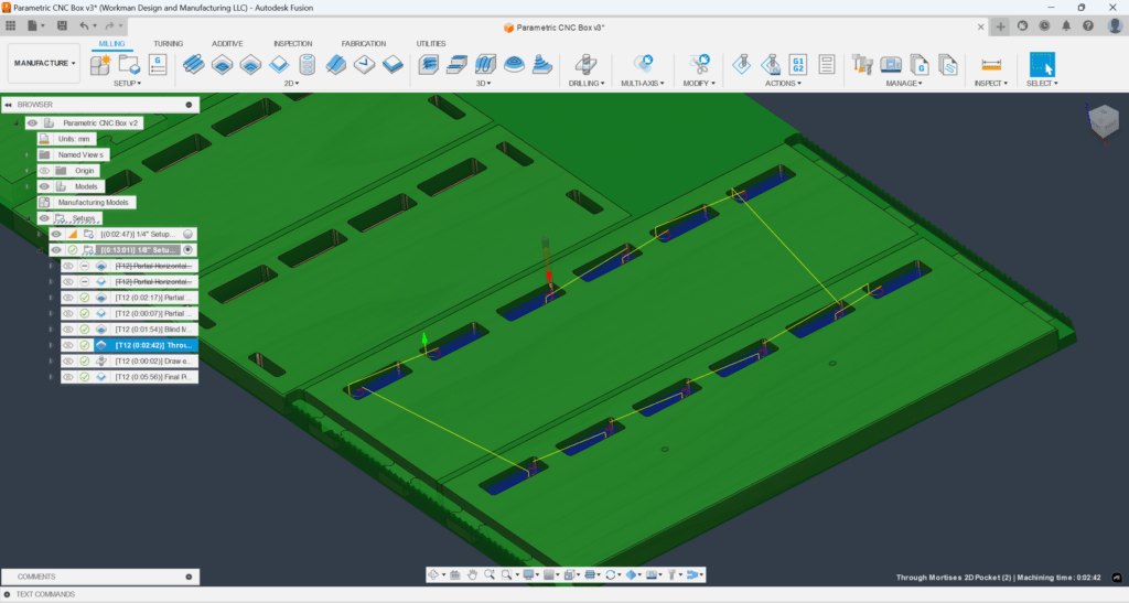
Step 5.4
- Through Mortises 2D Pocket
- This toolpath cuts the through mortises in the front and back
Step 5.5
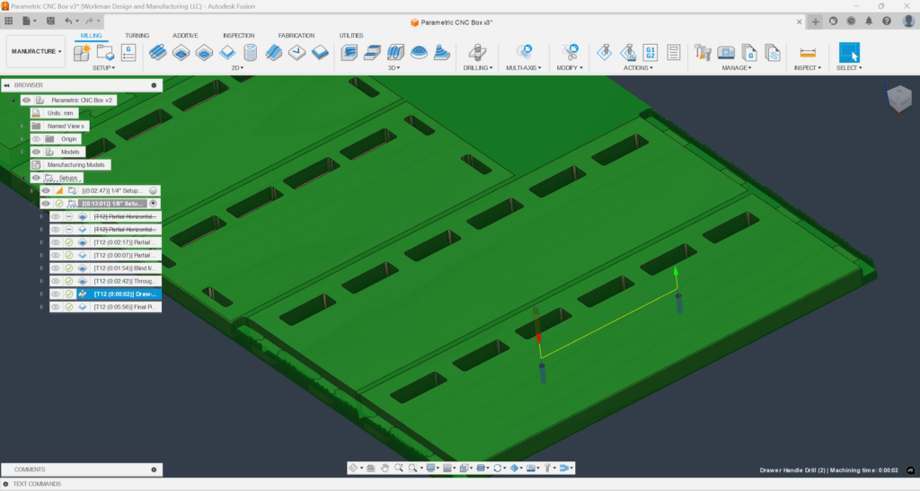
- Drawer Hole Drill
- This toolpath drills holes in the drawer front.
Step 5.6
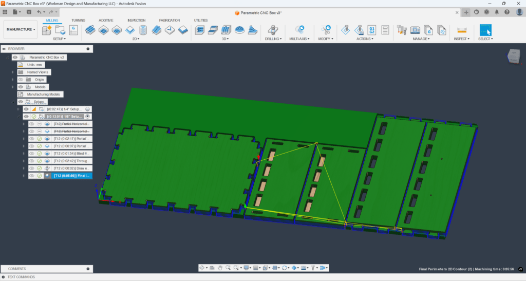
- Final Perimeters 2D Contour
- This toolpath cuts the final outline of your drawer pieces.
- Note: If you would like to use tabs to hold down the pieces, you must manually input their locations by right clicking on this toolpath > Edit >Geometry>Tabs>Manual Tabs.
Step 6: Toolpath Optimization #
Step 6.1
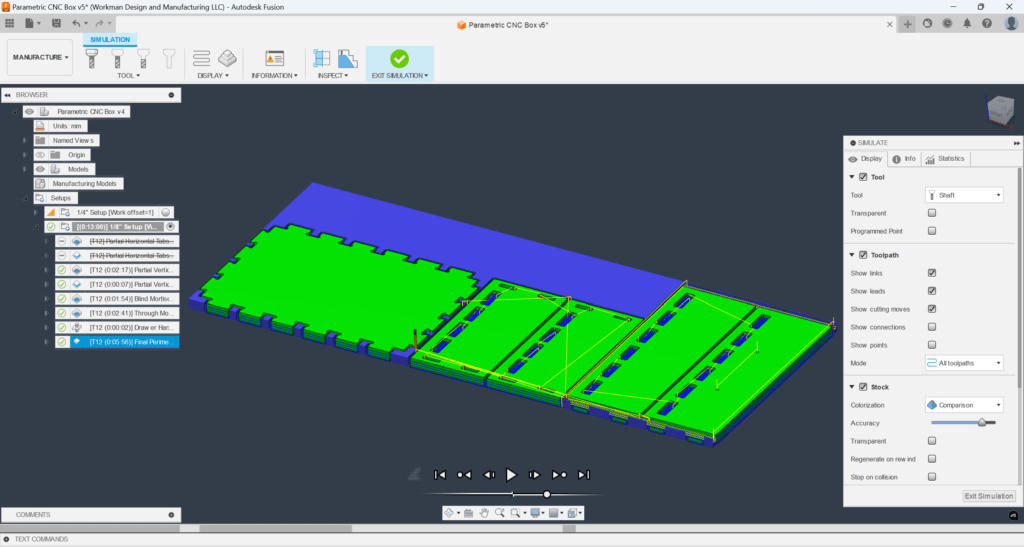
- By default, the toolpaths have a stepdown equal to the diameter of your bit and a stepover equal to half of the diameter.
- Note: This is a fairly conservative tool engagement and can be increased for a higher Material Removal Rate (MRR).
- The speeds and feeds should be determined based on your material and your endmill’s recommendations
Step 7: Assembly #
Step 7.1
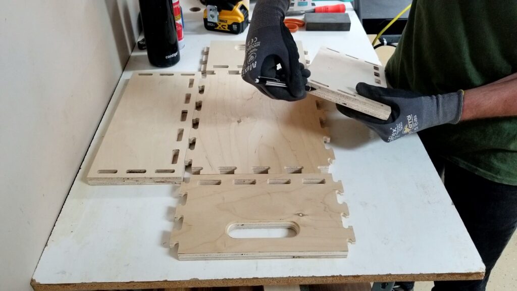
- If you are using a nailer to assemble the box, you will want to mark where the blind mortises are on the edges of your side panels.
- Once assembled, you cannot see where the side mortises are.
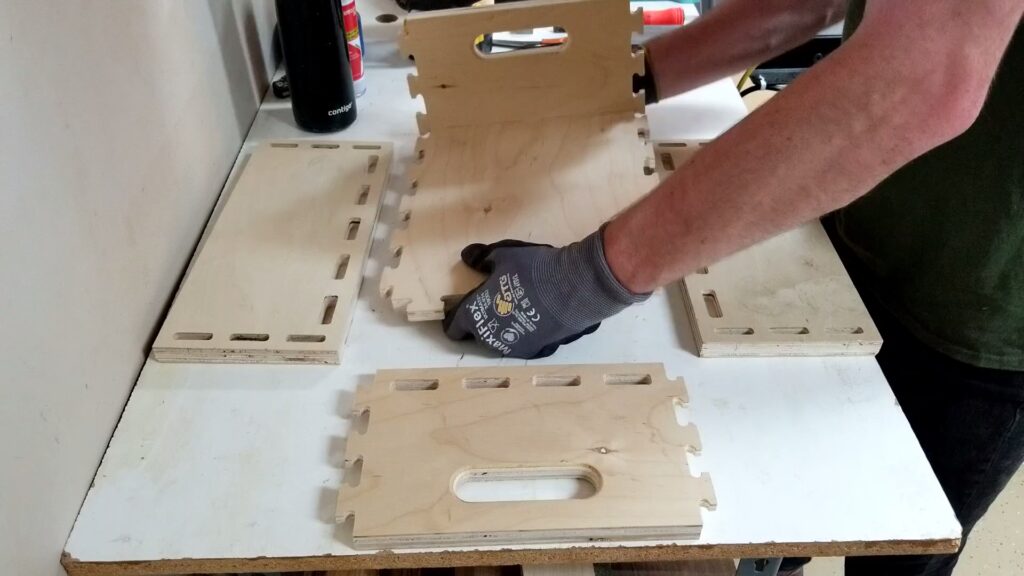
Step 7.2
- Insert your bottom panel into the through mortises of your front panel.
- Note: If using glue, you will want to put glue inside the through mortises before inserting.
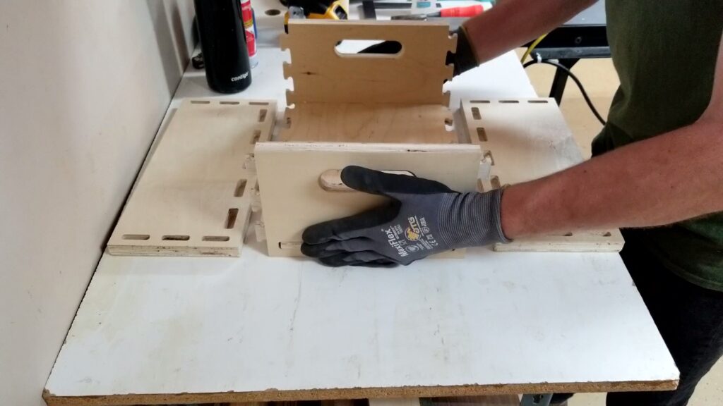
Step 7.3
- Repeat Step 7.2 with your rear panel.
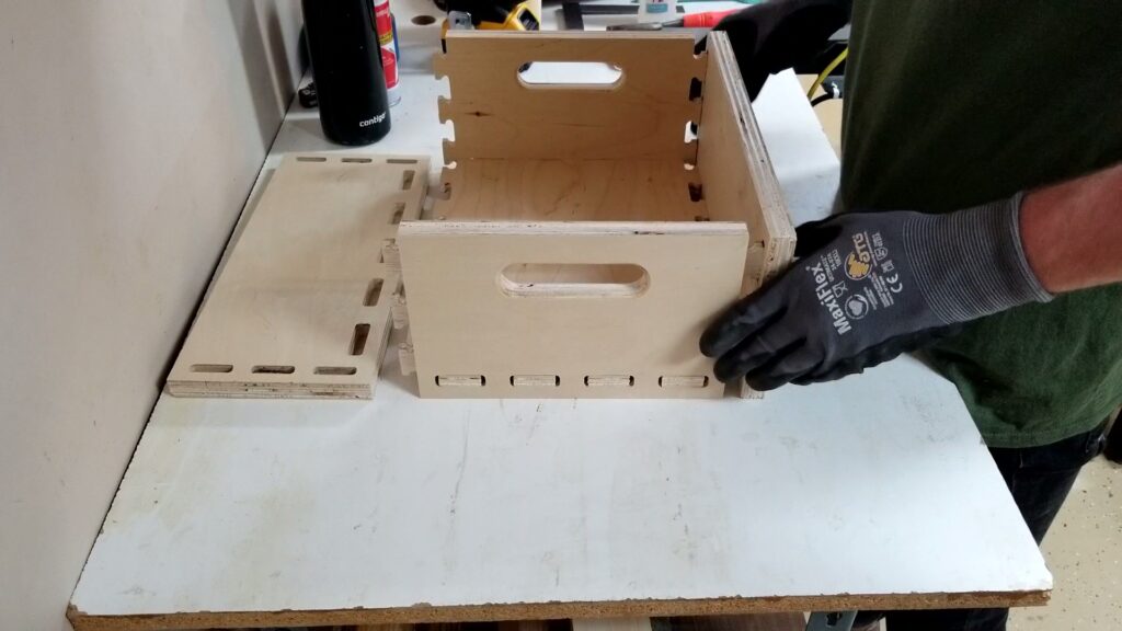
Step 7.4
- Line up one of your side panels with the previous assmebly and insert the tabs into the blind mortises.
- Note: If using glue, you will want to put glue inside the blind mortises before inserting.
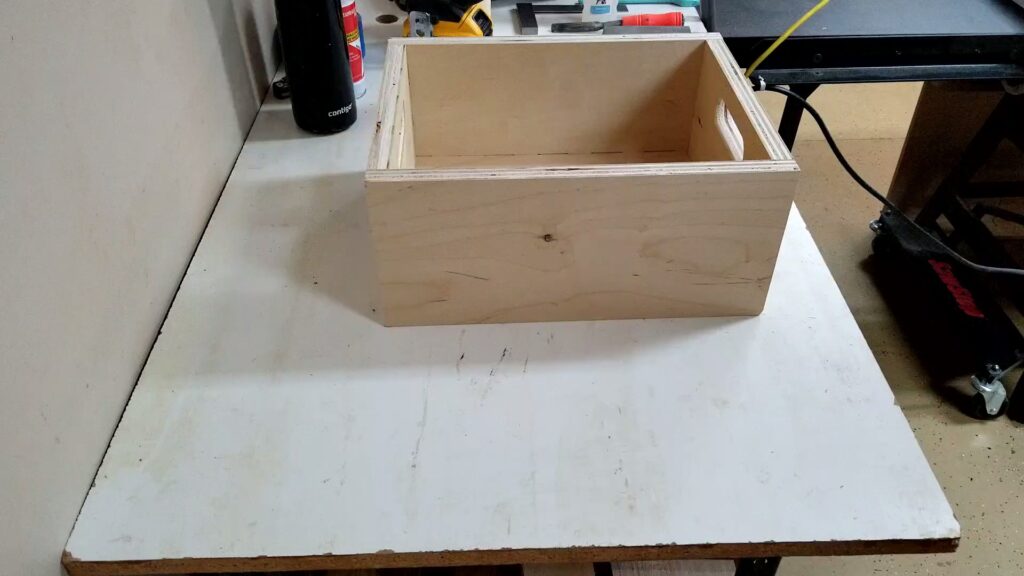
Step 7.5
- Repeat step 7.4 with your other side panel.
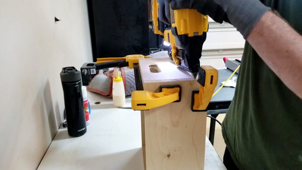
Step 7.6
- If using a nailer, shoot a nail through each tab, pinning it into its mortise.
- Note: You may want to clamp the joint tight to eliminate gaps before pinning.
Changelog #
| Date | Description |
|---|---|
| 2024/09/23 | Initial release |