Introduction #
This guide will take you step-by-step through the assembly of your Hermes Dust Boot. It will take approximately 15-30 mins.
This guide was created with a beta version of the Hermes Dust Boot, so parts may look slightly different. However, the assembly and build process is the exact same.
Please read through all steps before beginning to assemble your dust boot.
What you need: #
| Quantity | Part Description |
|---|---|
| 1kg | 3D Printer Filament (clear PETG recommended if you plan on making the optional view portal in Step 12) |
| 36 | 6mm x 3mm Neodymium Magnets |
| 1 | 12″ Dust Brush (or McMaster 1469N14/1469N15) |
| 2 | #8-32 x 55mm Hand Bolts |
| 2 | M5 x 8mm Countersunk Screws |
| 1 | Dust Hose (2.5″ recommended, 4″ optional) |
| 1 | Hose Clamp (or Zip Tie) |
| 1 | 65mm OD x 61mm ID x 100mm Length Acrylic Tube (optional, will additionally require 32 more magnets) |
| 1 | Small backlight (optional, only if Hermes Mount is printed out of clear PETG and if using the view portal) |
| Tools |
|---|
| 3D Printer |
| Super Glue (medium viscosity recommended) |
| Magnetic Compass (highly recommended) |
| #8-32 Tap (optional, but recommended) |
| Metric Hex/Allen Wrenches |
Step 1 – Print Parts #
3D Print the following parts in the orientation shown in the pictures. Recommended settings are:
- 2mm wall thickness (5x with 0.4mm perimeters)
- 30% cubic infill
- 2mm overall top and bottom thickness (7x with 0.3mm layers)
Ensure that the non-standard files match your specific setup. Each file is labelled “SpindleDiameter”-“ZAxis”-“MountDiameter”.
For example, on the files for a Z16 axis with an 80mm motor mount that has been adapted to a 65mm spindle, the label would read “65s-Z16-80”.
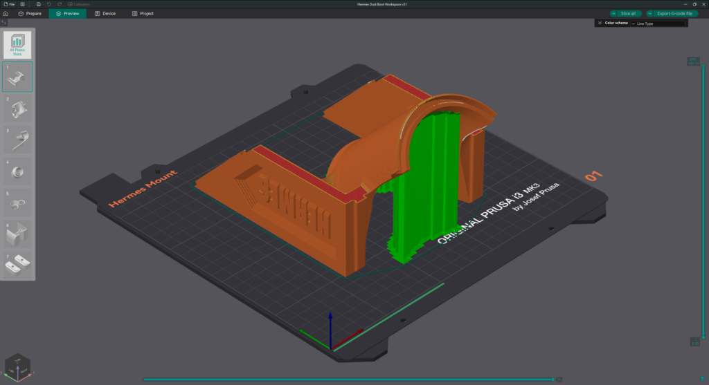
Step 1.1
- 1x Hermes Mount
- “Buildplate-only” supports may be needed if your printer struggles with steep overhangs.
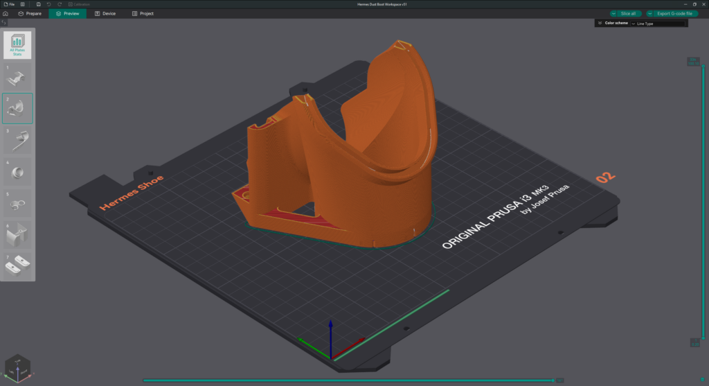
Step 1.2
- 1x Hermes Shoe
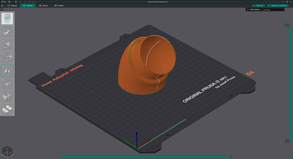
Step 1.3
- 1x Hose Adapter
- Measure the inside diameter of your dust hose and pick the Hose Adapter file that most closely matches that dimension.
- If there isn’t a Hose Adapter that matches your hose size, please contact us at j.workmandm@gmail.com
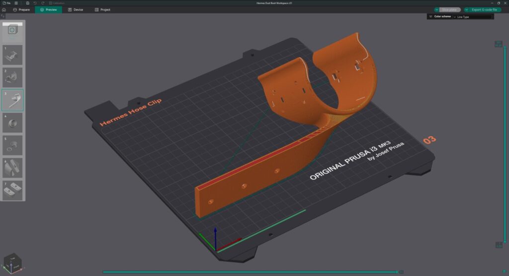
Step 1.4
- 1x Hermes Hose Clip
- Measure the outside diameter of your dust hose and pick the Hose Clip file that most closely matches that dimension.
- If there isn’t a Hose Clip that matches your hose size, please contact us at j.workmandm@gmail.com
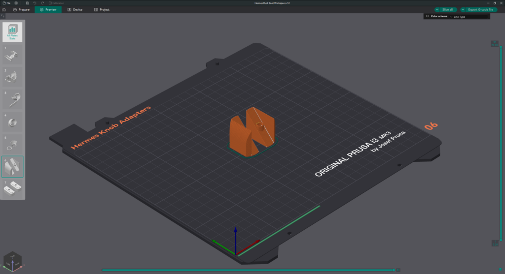
Step 1.5
- 1x Hermes Knob Adapters
- Print 1 each of left and right (mirrored).
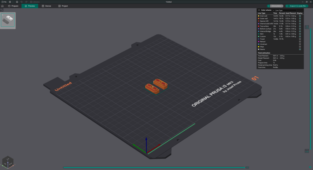
Step 1.6
- 2x Hermes Nuts
- These are optional if you already have the metal Onefinity Suckit Nuts.
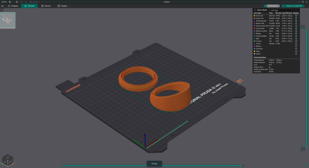
Step 1.7 (optional)
- 1x Hermes View Portal Ends
- This is an optional add-on that allows you to watch the milling in progress. It requires additional non-printed hardware.
- Note: The View Portal is currently only compatible with 2.5″ dust hoses.
Step 2 – Ream the Magnet Pockets #
Since 3D printers have a varying range of print tolerances, the magnet holes may need to be reamed with a drill bit the same diameter as your magnets (6mm or 1/4″).
Note: If using a drill for this step, do not push the drill too hard, otherwise the magnets will not sit at the correct height. You should only be applying enough pressure for the drill bit to ream the walls, not the bottom of the hole.
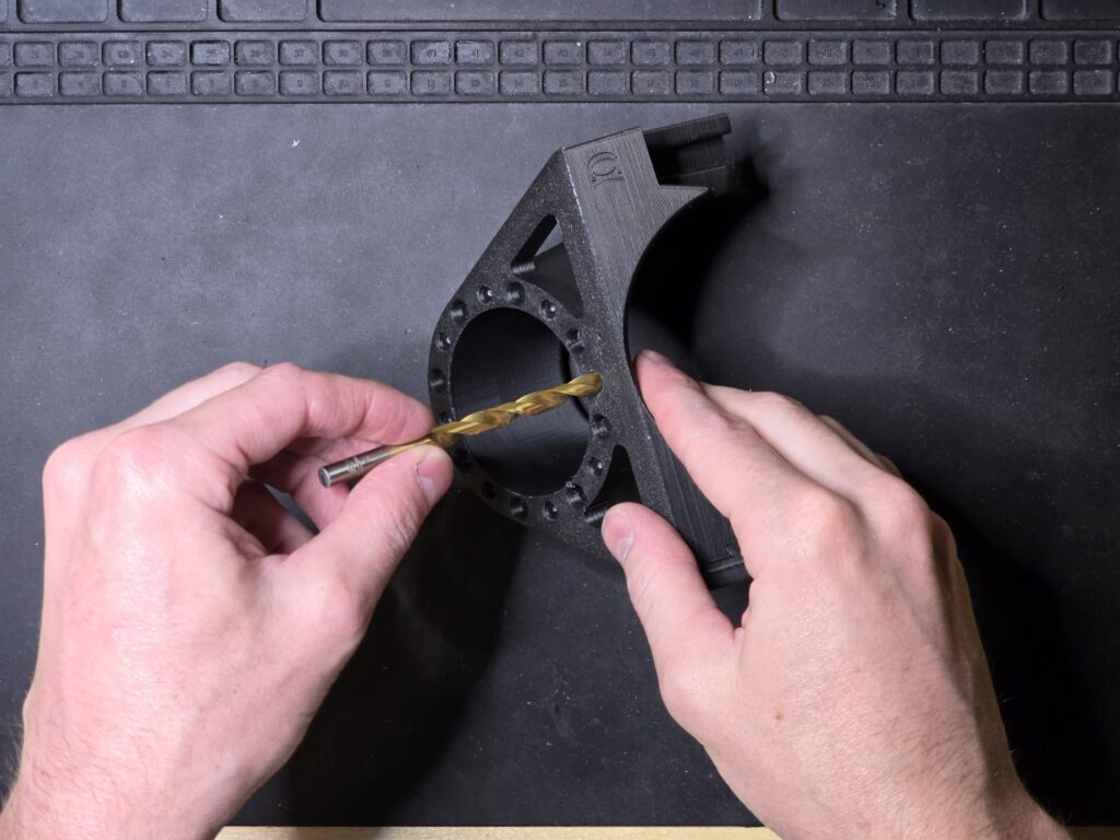
Step 2.1
- Gently ream each of the 18 magnet pockets on the Hermes Shoe.
- Note: Don’t forget the two magnet pockets on the back of the Hermes Shoe.
- Gently ream each of the 2 magnet pockets on the Hermes Mount.
- Gently ream each of the 16 magnet pockets on the Hose Adapter.
Step 3 – Install Magnets into the Hermes Shoe #
The magnetic hose connection uses the WDM7557 Magnetic Dust Port Specification.
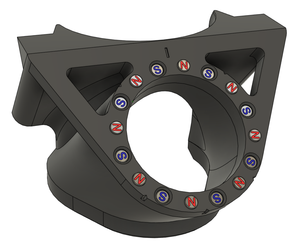
Step 3.1
- We will be installing magnets in the pattern shown in the picture.
- Refer to this digital render for the remaining 3.x steps.
- The north-pole-outward magnets are installed into shallower pockets and should protrude by ~1mm.
- The south-pole-outward magnets are installed into deeper pockets and should be recessed by ~1mm
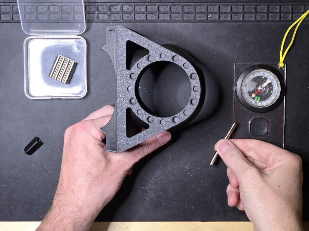
Step 3.2
- Determine the polarity of a stack of 8 magnets using a magnetic compass.
- It may be helpful to mark each of the South Poles with a marker so you don’t lose track of the polarity
- Note: The compass will always point towards the South Pole of a permanent magnet since opposites attract.
- If you do not possess a compass, arbitrarily assign a Master magnet’s North and South poles, and use that to identify polarity.
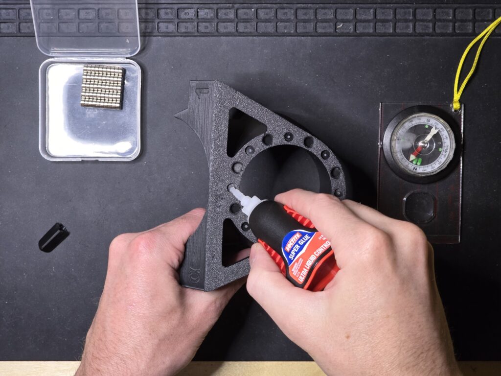
Step 3.3
- Put a drop of super glue in the shallower “North” pockets
- Note: Picture shown is an older version of the Hermes, so refer to the digital render in Step 3.1 above for the correct pockets. The older version had the Magnet pattern rotated 11.25 degrees (1/32 of a rotation) counterclockwise.
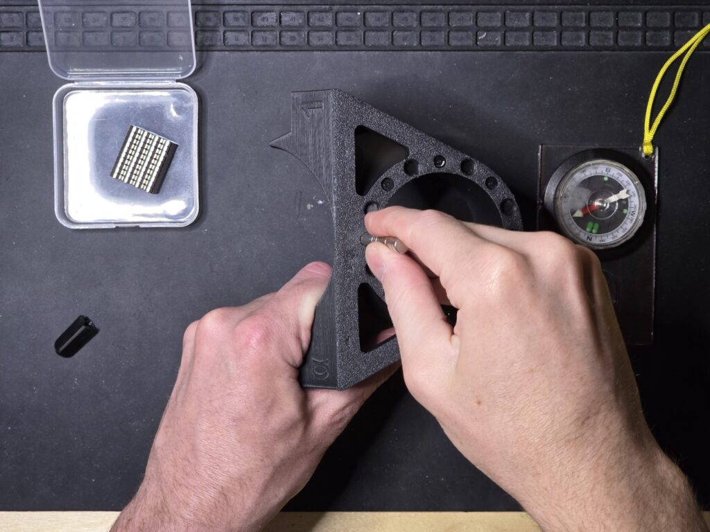
Step 3.4
- Install a magnet into each of the shallower pockets so that its North pole will face outwards.
- Note: Refer to the digital render in Step 3.1 above for the correct pockets.
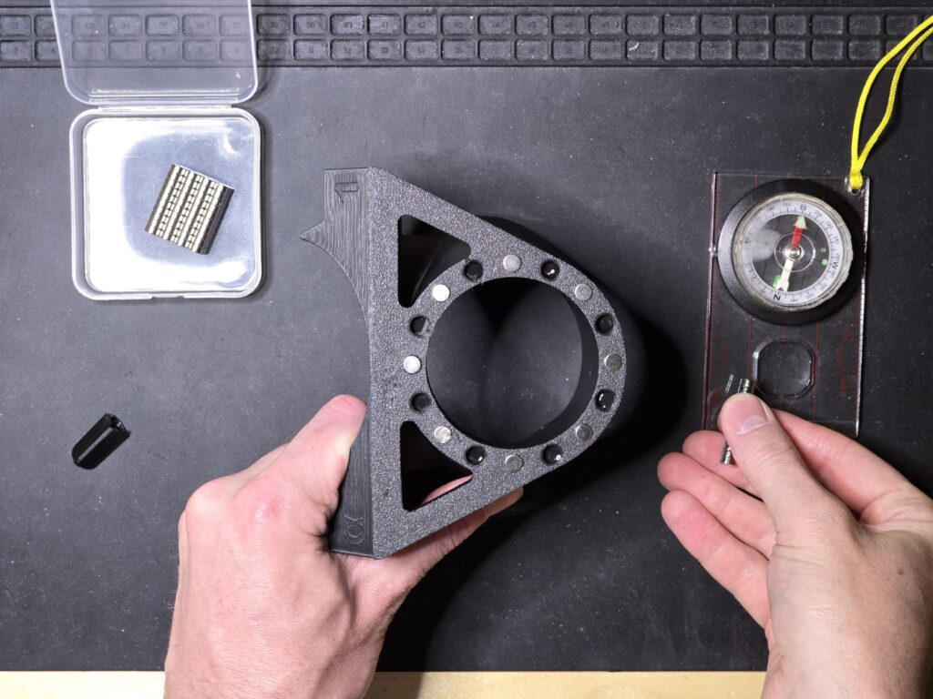
Step 3.5
- Put a drop of super glue into each of the deeper “South” pockets
- Note: Refer to the digital render in Step 3.1 above for the correct pockets.
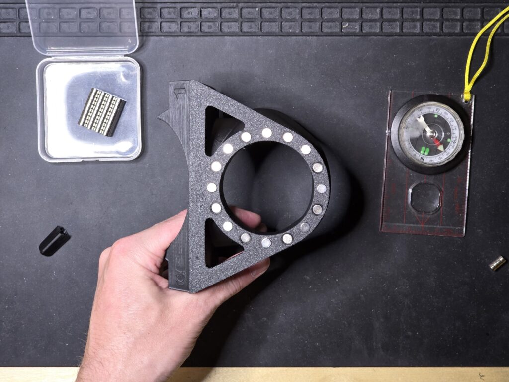
Step 3.6
- Determine the polarity of a stack of 8 magnets and install them into the deeper pockets with their South poles facing outwards.
- It is easiest to check this by making sure they repel the previously placed North-outward magnets.
- Note: Refer to the digital render in Step 3.1 above for the correct pockets.
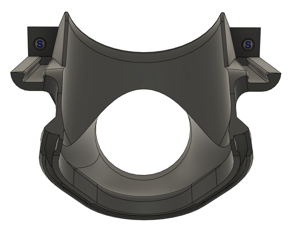
Step 3.7
- Following the same procedure as previously shown, with a drop of super glue, install two magnets in the back of the Hermes Shoe so that their South poles face outwards.
- The magnets should be flush with the surface.
- Note: Refer to this digital render.
Step 4 – Install Magnets into the Hermes Mount #
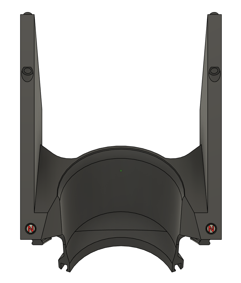
Step 4.1
- Following the same procedure as previously shown in Step 3, with a drop of super glue, install two magnets in the front of the Hermes Mount so that their North poles face outwards.
- The magnets should be flush with the surface.
- Note: Refer to this digital render.
Step 5 – Install Magnets into the Hose Adapter #
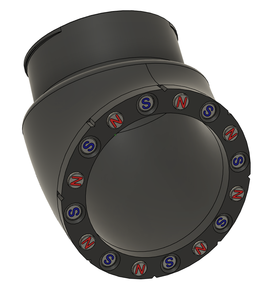
Step 5.1
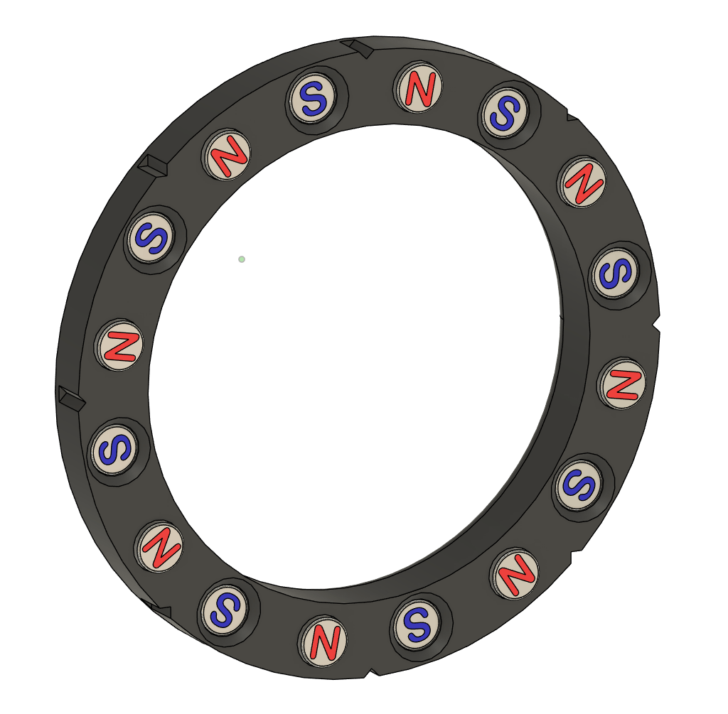
- Following the same procedure as previously shown in Step 3, with a drop of super glue, install sixteen magnets in the Hose Adapter, matching the pattern shown in this digital render.
- Note: A North-outward magnet will always be to the right of an indicator notch.
- It is recommended to install the 8 North-outward magnets first, then install the 8 South-outward magnets.
- Note: Refer to this digital render.
Step 6 – Insert the Dust Brush #
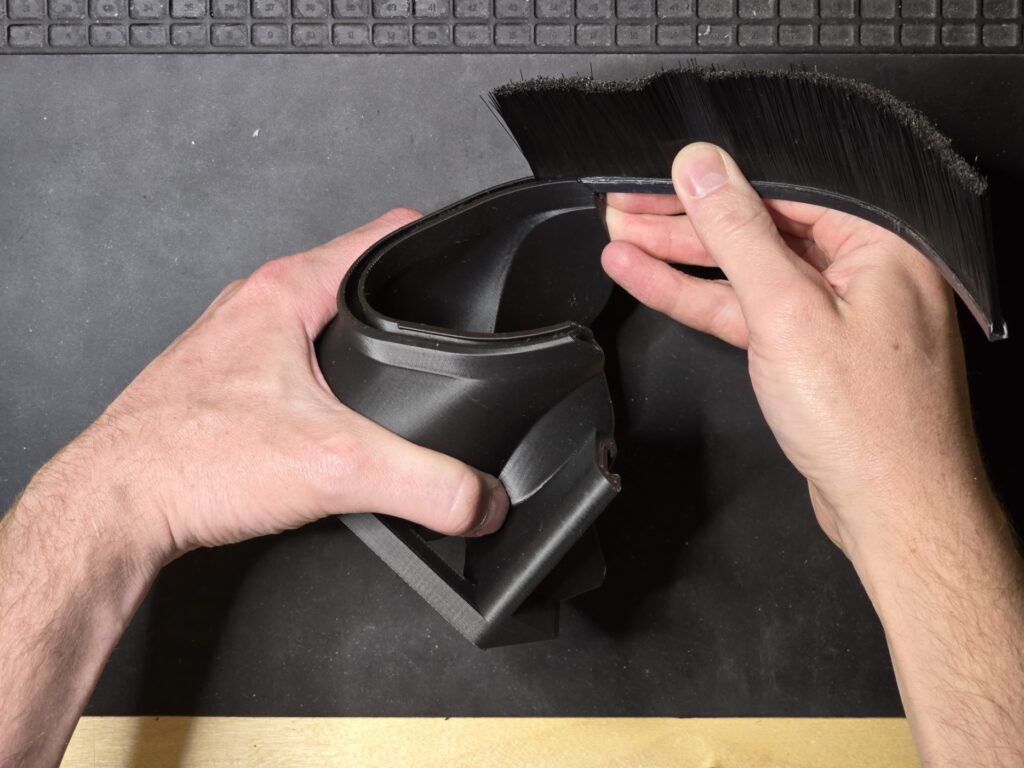
Step 6.1
- Insert the dust brush into the Hermes Shoe’s channel starting at one end.
- Note: It should be a firm fit, but it should slide in fairly easily.
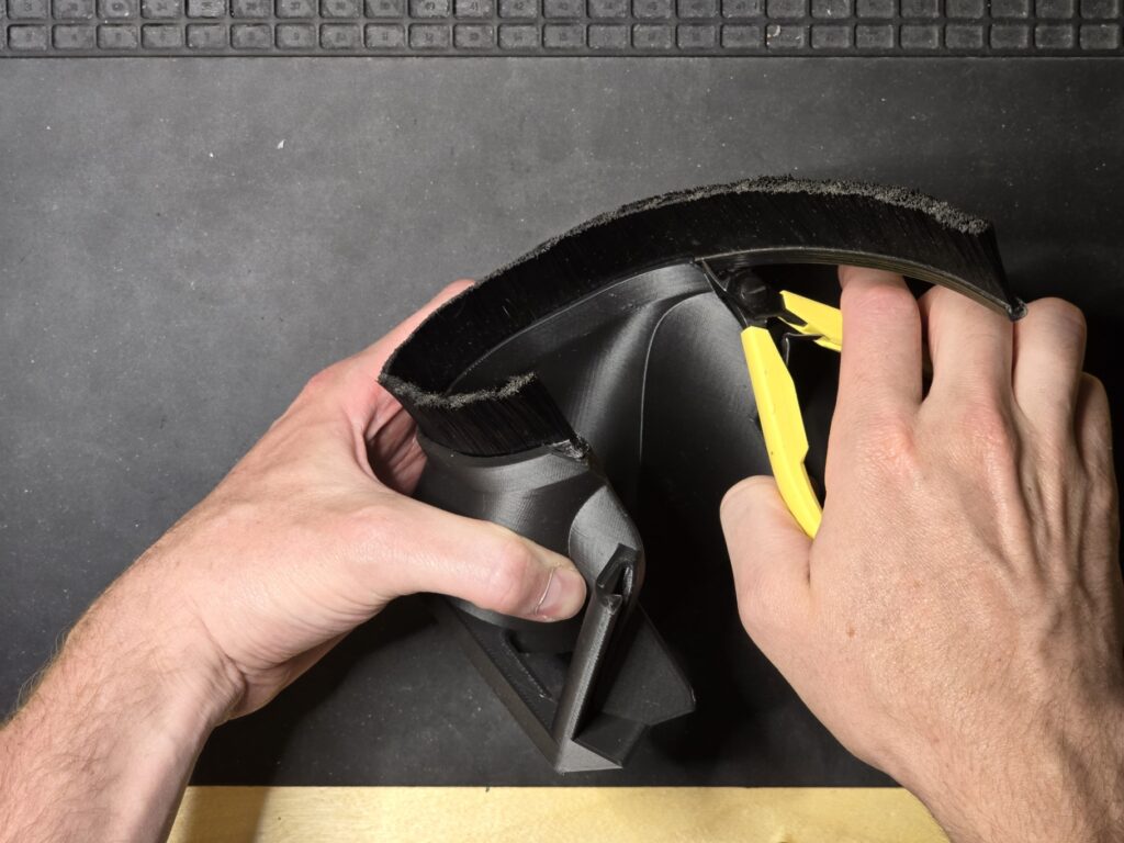
Step 6.2
- Make sure the dust brush is flush on one end.
- Score and flush cut the other end to length.
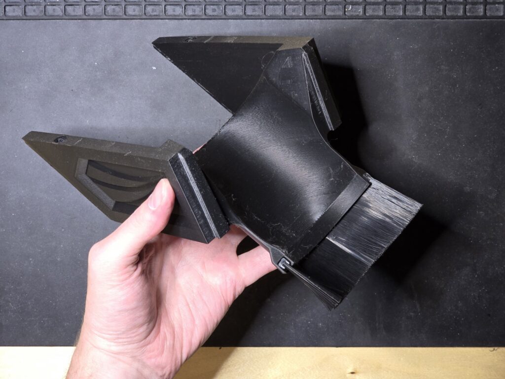
Step 6.3
- With the leftover brush, repeat steps 6.1 and 6.2 with the Hermes Mount.
Step 7 – Prepare to install the Hermes #
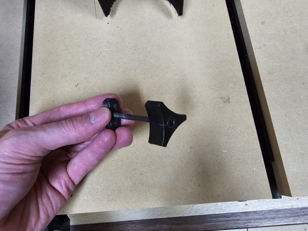
Step 7.1
- If using the Hermes Nuts, run an #8-32 tap into both nuts to create threads for the Suckit Knobs.
- Alternatively, you may manually use the Suckit Knobs to self-tap threads into the Hermes Nuts.
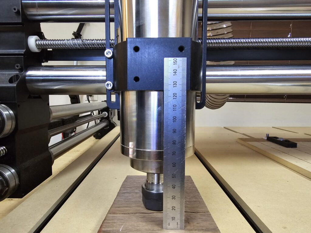
Step 7.2
- Shift your spindle in the Onefinity Mount such that there is at least 125mm between the spindle mount and the end of the collet nut with no bit installed.
- It is easiest to loosen the spindle in its mount, rest it on a block on your wasteboard, and then jog the spindle mount up or down.
Step 8 – Install the Hermes Mount #
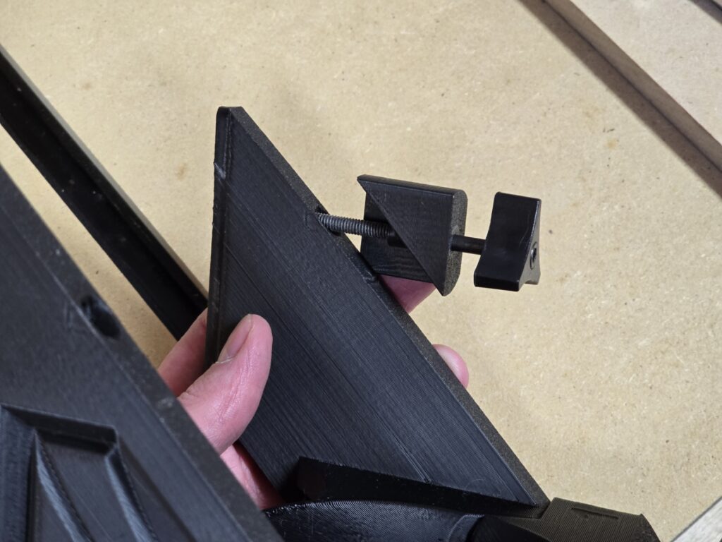
Step 8.1
- Insert the Suckit Knobs through the Hermes Knob Adapters and through the Hermes Mount as shown.
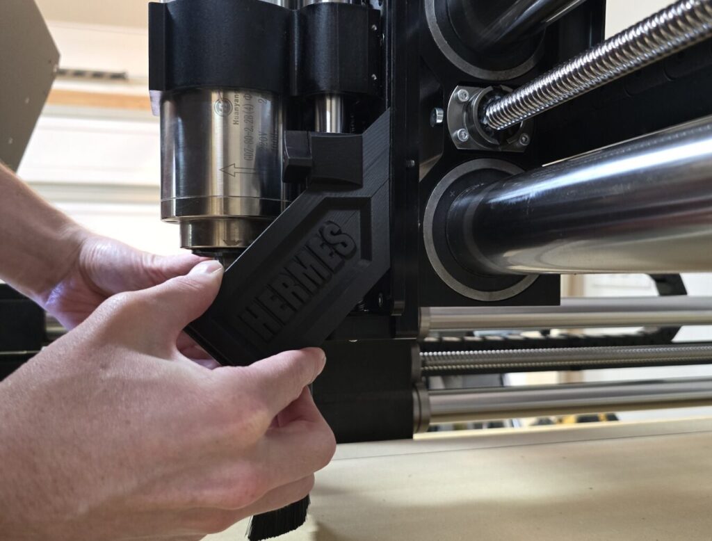
Step 8.2
- Place the Hermes Mount behind the spindle and into the slots of the Z20 slider.
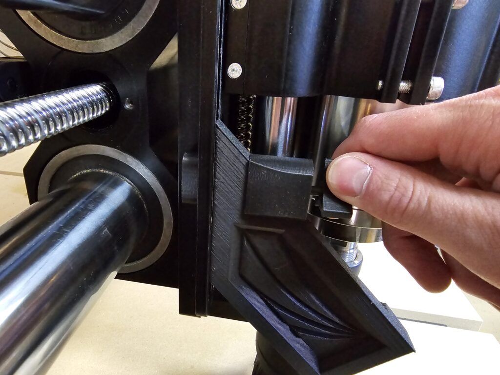
Step 8.3
- Place the Hermes Nuts behind the Z20 slider slots and tighten the Suckit Knobs into them.
- Note: Do not overtighten! The Hermes Mount should be just tight enough that it still slides with a few pounds of force.
- Alternatively, you may use the original Onefinity Suckit Nuts.
Step 9 – Install the Hermes Shoe #
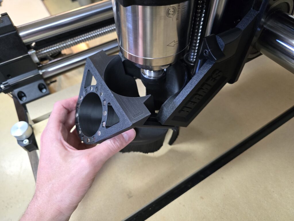
Step 9.1
- Slide the Hermes Shoe onto the Hermes Mount as shown.
- Note: It is fine, even preferable, if there is a bit of friction. However, if it cannot fully seat onto the Hermes Mount, you may need to sand the tapered dovetail slides.
Step 10 – Install the Hermes Hose Clip #
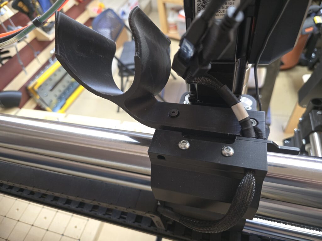
Step 10.1
- Secure the Hermes Hose Clip to the top of your Onefinity X-carriage using two M5x8mm countersunk screws.
- Alternatively, you may use two M6 screws into the rear two holes.
- Note: Picture shows the rear of the Onefinity Z20 Slider/X carriage.
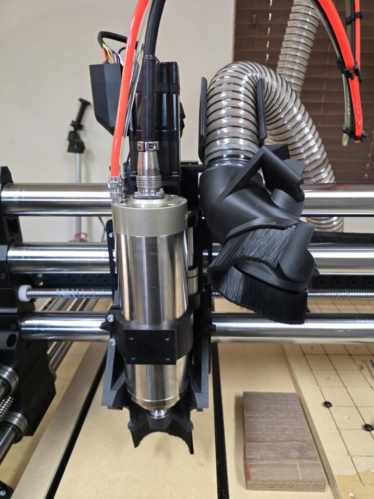
Step 10.2
- Note: The Hose Clip manages the dust hose while in motion, but it can also be used to stow the shoe out of the way as shown.
- Note: The Hose Clip has spots to Zip-tie your spindle cable and water cooling lines on either side, depending on your setup.
Step 11 – Install the Hose Adapter #
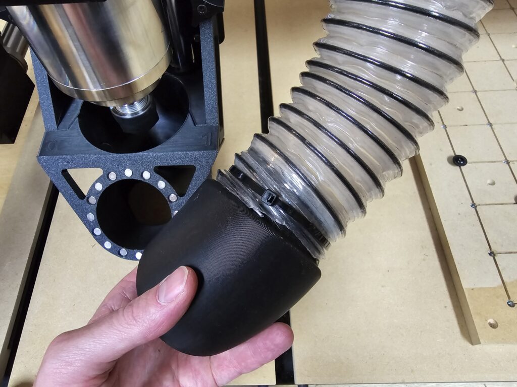
Step 11.1
- Insert your Hose Adapter into your Dust Hose and secure it with a Hose Clamp or a Zip-tie.
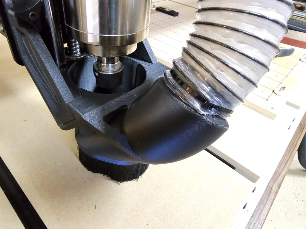
Step 11.2
- Magnetically snap the Hose Adapter to the Hermes Shoe.
Step 12 – Assemble the Hermes View Portal (Optional) #
The Hermes View Portal is an optional accessory that provides limited visibility of the bit and sawdust while performing an operation. It is not required.
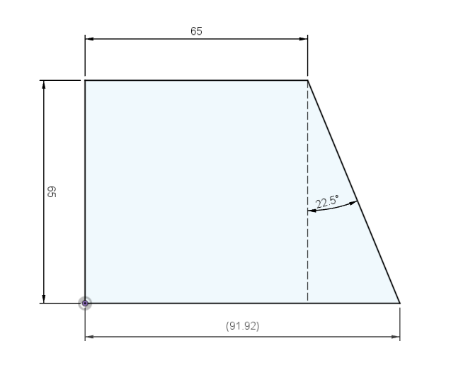
Step 12.1
- Cut a piece of 65mm OD x 61mm ID Acrylic Tube at a 22.5 degree angle, such that the short side is at least 65mm long.
- Note: Tubes longer than this have diminishing returns on visibility of the bit.
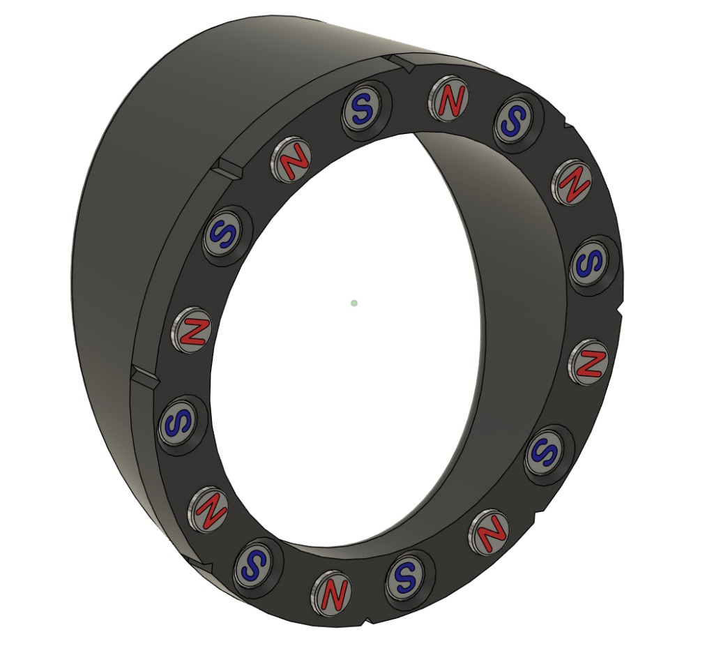
Step 12.2
- Following the same procedure as previously shown in Step 3, with a drop of super glue, install sixteen magnets in the View Portal Angled End matching the polarity pattern shown in this digital render.
Step 12.3
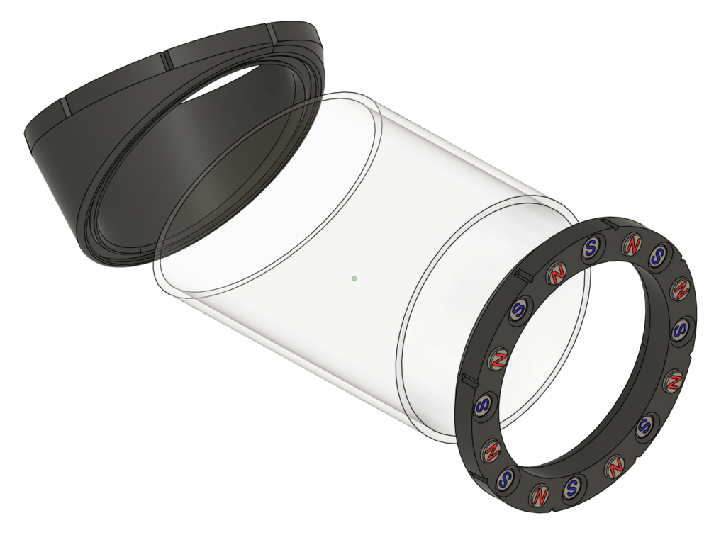
- Following the same procedure as previously shown in Step 3, with a drop of super glue, install sixteen magnets in the View Portal Straight End matching the pattern shown in this digital render.
Step 12.4
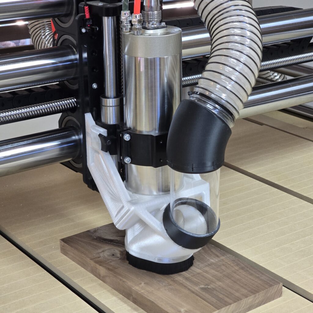
- Super glue the 22.5 degree cut end of the Acrylic Tube into the View Portal Angled End.
- The angle of the tube should be symmetric with the glare shield.
- Super glue the straight end of the Acrylic Tube into the View Portal Straight End, matching the orientation notches with the previously installed View Portal Angled End.
Step 12.5
- Insert the view portal magnetically between the Hermes Shoe and the Hose Adapter.
- If you printed your Hermes Mount out of clear PETG, you may optionally add a Small Backlight to the bottom of your X-axis Carriage for improved visibility.
Step 13 – Hermes is Complete! #
Step 13.1
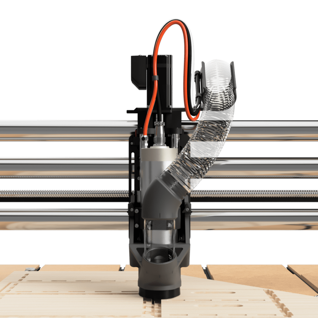
- Your Hermes Dust Boot is complete and ready to use!
- Enjoy a dust-free CNC!
Changelog #
| Date | Description |
|---|---|
| 2024/10/11 | Added note about file naming scheme for non-standard parts |
| 2024/10/03 | Added optional backlight |
| 2024/09/27 | Initial release |